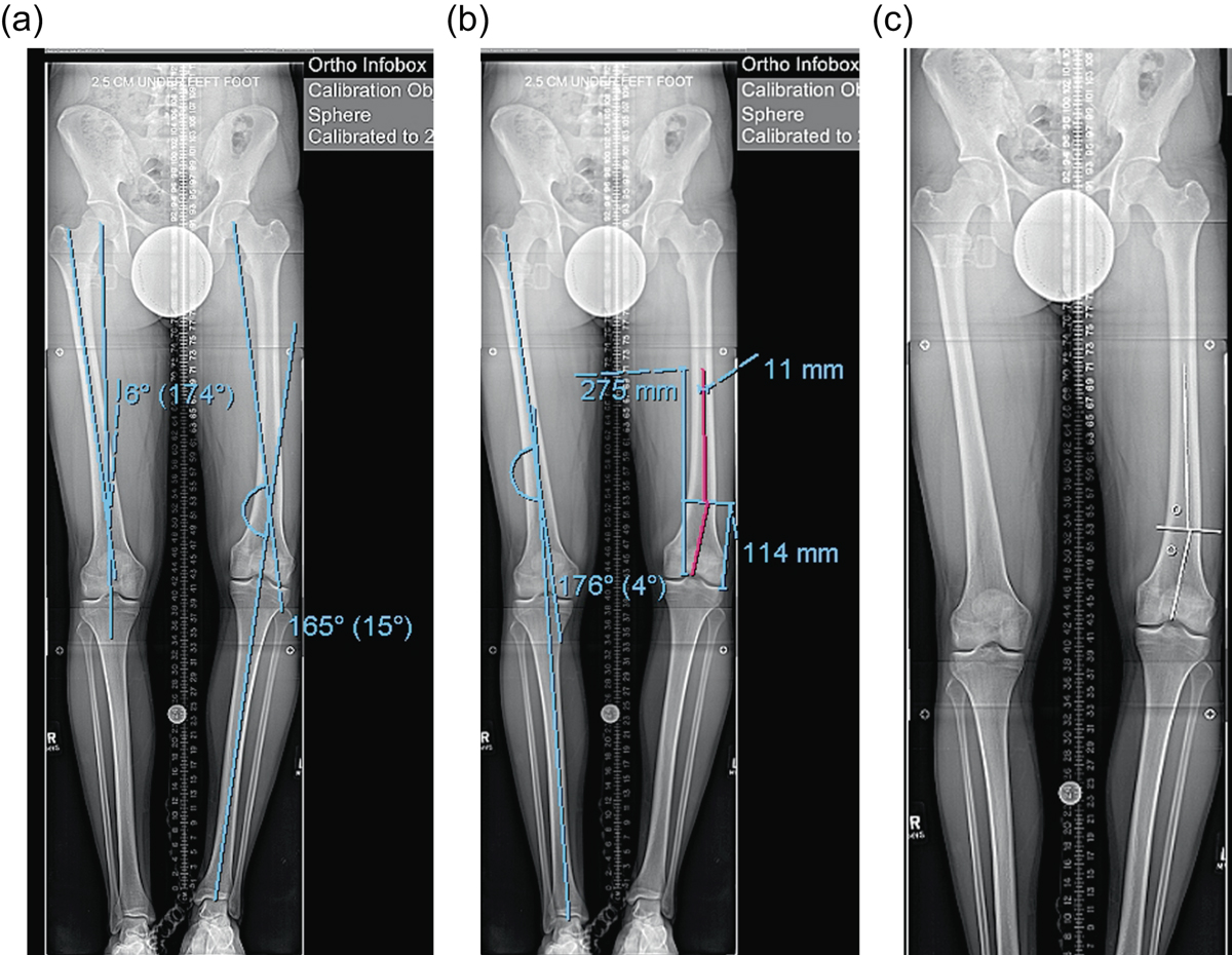
Figure 2.
Download original image
(a) This 51 inch AP radiograph allows for deformity planning with correction of varus and shortening. The mechanical axis planning is used to determine the magnitude and location of the deformity. (b) The red lines show the planned path of the ILN that will ensure correction of mechanical axis. The lines also show the length of the nail. (c) The white lines are placed to designate the path of the nail, and the circles are used to mark the location of the blocking screws. These radiographic plans are brought into the OR for comparison with intraop fluoroscopy shots.
Current usage metrics show cumulative count of Article Views (full-text article views including HTML views, PDF and ePub downloads, according to the available data) and Abstracts Views on Vision4Press platform.
Data correspond to usage on the plateform after 2015. The current usage metrics is available 48-96 hours after online publication and is updated daily on week days.
Initial download of the metrics may take a while.