Figure 3
Download original image
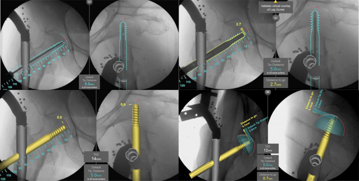
After inserting the guidewire along the outline displayed on the ADAPT monitor, the predicted position and length of the lag screw are displayed in a setting where the TSD is 5 mm. When the lag screw is actually inserted, the display shows how many more mm it needs to be inserted before the TSD will be in the 5 mm position. In addition, TAD can be checked at any time during the operation. After the lag screw has been installed, the position of the lag screw is displayed in 3D.
Current usage metrics show cumulative count of Article Views (full-text article views including HTML views, PDF and ePub downloads, according to the available data) and Abstracts Views on Vision4Press platform.
Data correspond to usage on the plateform after 2015. The current usage metrics is available 48-96 hours after online publication and is updated daily on week days.
Initial download of the metrics may take a while.